Ads
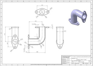
Step-by-Step Instructions to Model This in SolidWorks:
Ads
Step 1: Create Base Pipe (Vertical Component)
Open SolidWorks > New Part.
Choose Front Plane > Sketch.
Create a circle of Ø72 mm (outer diameter).
Offset it inward by wall thickness (say 3 mm) to hollow it.
Use Extruded Boss/Base to create a 120 mm vertical extrusion.
Ads
Step 2: Create Horizontal Pipe (Elbow)
Choose Right Plane > Sketch.
Draw a centerline, followed by a quarter circle (R72) employing the arc tool (elbow radius).
Draw the pipe thickness (offset arc by ~3 mm inside).
Employ Extruded Boss/Base along this path to form the elbow (or Swept Boss/Base if necessary).
Combine it with the vertical pipe.
Ads
Step 3: Make Flange
On the top face of the vertical pipe, draw a flange shape:
Draw an ellipse-type flange (120 mm long, 60 mm wide).
Add 2 bolt holes Ø10 mm as indicated in top view.
Extrude the flange upward by 10 mm.
Similar steps are to be repeated for the horizontal end flange of the elbow.
Ads
Step 4: Make the Sectioned Support
On the bottom, draw and extrude the support rib and details as indicated in the section view.
Add cut extrudes for slots and holes.
Ads
Step 5: Add Fillets
Add fillets of R2, R10, etc. as specified in the drawing.
Use Fillet tool to perform internal/external rounding.
Ads
Step 6: Add Material and Appearance
Specify material such as Cast Iron or Steel (optional).
Assign appearance to render similar to the view rendered.
Ads
Step 7: Save and Create Drawing (Optional)
Proceed to File >
Make Drawing from Part to create 2D views.
Ads

No comments:
Post a Comment